
WHICH TRUCK WAS MY CONCRETE BRIDGE DESIGNED TO CARRY (IN QUEENSLAND, AUSTRALIA)?
Chris Dowding, Director – Structures Group
TOD Consulting, March, 2017
Update Revsion B, April, 2017
Sometimes, the old drawings for a concrete bridge cannot be found. Sometimes, the specific drawing sheet or specification, indicating the design load, has gone missing.
How can you estimate what the original load capacity of the bridge was?
One way is by first work out an approximate age of the bridge:
- Often bridges have a date plate fixed to one Abutment, indicating the year of construction. Bridges built by Queensland’s TMR (the State Road Authority) should usually have a date plate. Have a look on site.
- If you have any of the drawings, there should be dates at the bottom indicating when it was designed and/or when the drawings were issued for construction
- The year of design and the year of construction are usually different. Often these activities occurred 1 to 2 years apart. For example, if the bridge was designed in 1968, it was probably built in 1969 or 1970. And vice versa
- Another way to estimate age, is by looking at the barrier rails (if there are any). Barrier rails changed in style (and containment capacity) over the decades. Some examples follow below.
Barrier rail styles can indicate bridge age
Prior to 1976:
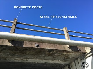
Steel pipe rails (circular hollow section) and concrete posts (Memorial Drive Bridge, Tewantin, built 1968)
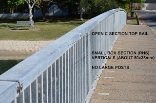
Small box section verticals for pedestrians (about 50x25mm) and C-shaped top rail, no large posts provided (Witta Circle Bridge, Noosa Heads, built 1972)
1976 to 1992:
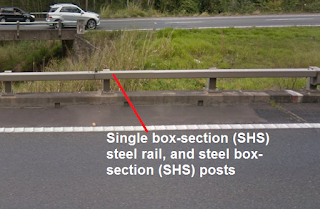
Single box-section (SHS or RHS) steel rail, and steel box-section (SHS) posts (Bruce Highway northbound bridge, between Pumicestone Road and Steve Irwin Way exits, built circa ????). See behind: Steel pipe rail (circular hollow section) and concrete posts on southbound bridge, built earlier circa 1970.
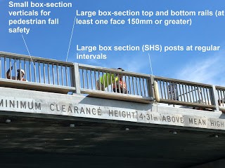
Small box section verticals for pedestrians. Large box-section top and bottom rails (at least one face 150mm or greater), and large box section posts at regular intervals, for traffic (Munna Point Bridge, Noosa Drive, Noosa Heads)
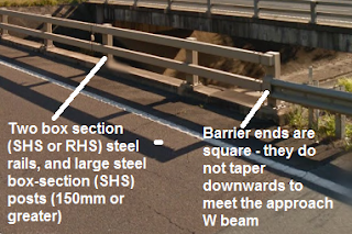
2 x box section (SHS or RHS) steel rails, and large steel box-section (SHS) posts (150mm or greater). Barrier ends are square – they do not taper downwards to meet the approach W/Thrie beam. (Bruce Highway overpass – Steve Irwin Way southern end, built circa 1985
1992 to 2004:
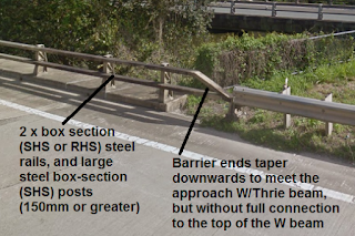
2 x box section (SHS or RHS) steel rails, and large steel box-section (SHS) posts (150mm or greater). Barrier ends a taper downwards to meet the approach W/Thrie beam, but without full connection to the top of the W beam. (Bruce Highway – Yandina – South Maroochy River crossing, built circa 1997)
2004-2017:
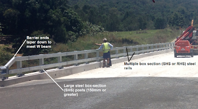
2 x box section (SHS or RHS) steel rails, and large steel box-section (SHS) posts (150mm or greater). Barrier ends taper downwards to meet the approach W/Thrie beam with full connection to W beam (Pickering Bridge, Moy Pocket Rd, Gheerulla, built 2013)
Converting bridge age into a design truck load
The next step is to find a copy of the Design Code/Standard that was current when the bridge was designed. The following list is not exhaustive, and will be updated as our research proceeds:
- 1970 Highway Bridge Design Specification
- 1976 NAASRA Bridge Design Specification
- 1992 Austroads Bridge Design Code
- 1996 HB77 Australian Bridge Design Code – a reproduction of the 1992 Austroads Bridge Design Code
- 2004 Australian Standard AS5100-2004 Bridge Design
- 2017 Australian Standard AS5100-2017 Bridge Design
For a preliminary estimate of a bridge’s original load capacity, refer the the applicable Design Code (that was in use at the time of the bridge’s design), and find the standard design truck. We have summarised the design truck for each time period, below. Again, the following list is not exhaustive, and will be updated as our research proceeds
Standard design trucks over the decades
Bridges designed between 1955 – 1976:
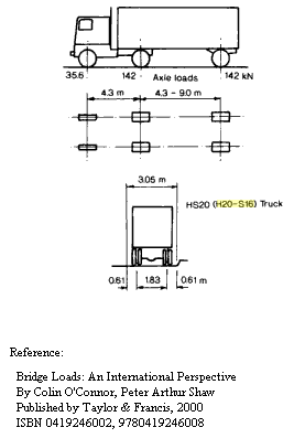
The H20-S16 (33 tonnes) was the standard design truck, for main roads and highways, in the 1970 Bridge Design Specification. Smaller trucks were sometimes allowed for on smaller roads
– The H20-S16 is also known as the MS18 (see AS5100.7 for drawing of MS18).
– It is probable that the H20-S16 was the standard load for main roads and highway concrete bridges dating at least from 1955. The US added it as a design load to bridge specifications in that country from 1944.
Bridges designed between 1976-2004:
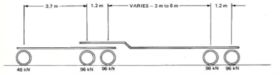
The T44 (44 tonne semi-trailer) load was introduced with the 1976 NAASRA Bridge Design Specification. The T44 remained as the standard design load for bridges, in the 1992 Austroads Bridge Design Code up until around 2004, when “AS5100.2 2004 Bridge Design – Part 2: Design Loads” was released.
– In addition, an A14 axle load (2 wheels x 7.1 tonnes each) that had to be checked, often gave worse effects that T44 on short spans. This was later changed to a single W7 wheel load (1 wheel x 7.1 tonnes) – but effectively the stresses imposed on the bridge were the same as the A14.
– There were also Heavy Platform Loads (HLP-320 and HLP-400) (320 tonnes and 400 tonnes respectively) that were common additional design loads for TMR bridges, less common but sometimes required for Council bridges. If this isn’t shown on the drawings, it is safer to assume these weren’t allowed for.
– Sometimes, for shorter spans (10m or less, which were common at the time), the stresses induced in a bridge by the earlier H20-S16 truck (33 tonnes) and the replacement T44 (44 tonnes) can be quite similar. But this would need to be checked by someone experienced, on a case by case basis.
Bridges designed between 2004-2017:
The SM1600 load was introduced with “AS5100.2 2004 Bridge Design – Part 2: Design Loads” in 2004. The SM1600 load has remained as the standard design load for bridges until March 2017, when a major revision of the AS5100 was released.
– There was also a W80 axle load (2 wheels x 8.1 tonnes) that had to be checked, which gave worse effects on short spans
– Sometimes bridge owners and authorites also required their bridges to be designed for Heavy Load Platforms (HLP320 and/or HLP400). But if this isn’t shown on the drawings, it is safer to assume these weren’t allowed for.
Bridge designed March 2017 onwards:
Stay posted for an update on this one. The new Standard, AS5100-2017 Bridge Design, has just been released
CONCLUSIONS
This paper gives readers a method to obtain a preliminary estimate for the original design load capacity of a bridge, when the original drawings are no longer available:
- The method can’t be used to determine the present load capacity of the bridge, in the present day:
- Many bridges lose strength over time, due to corrosion, cracking and other dilapidation effects.
- Some bridges have been altered since being constructed
- Some bridges have been strengthened
- The only way to be certain of a bridge’s present load capacity, is to do the work to determine a load rating. AS5100.7 Bridge Design – Rating of existing bridges lays out methods to do this. Alternatively, a suitably qualified Bridge Engineer would be able to assist you
I’d be happy to receive constructive feedback for this article, with the aim of improving its usefulness.
REFERENCES
- AS5100.7-2004 Bridge Design – Rating of Existing Bridges
- 1976 NAASRA Bridge Design Specification
- https://en.wikipedia.org/wiki/Bruce_Highway
- Bridge Loads – An International Perspective, 2000, O’Connor et al
Disclaimer Note: TOD Consulting has prepared this fact sheet in good faith, as general information only. This factsheet should not be used as a substitute for seeking professional engineering advice, for your specific circumstances. March 2017 by Chris Dowding – TOD Consulting Pty Ltd